Contact: Mr.Wang 13585000194 / 15861488616
 Web: www.wxkbjx.com
 Add: Yuanqiao Road, Yixing City
Product List
PRODUCT LIST-
CONTACT US
- Contact: Mr.Wang
- Mobile: 13585000194
- Mobile: 15861488616
- Tel: 0510-85388408
- Fax: 0510-85388408
- Web: www.wxkbjx.com
- E-mail: sales@wxkbjx.com
- 502492439@qq.com
- Add: 42 Yuanqiao Road, Yixing
- Economic Development
- Zone, Wuxi City
Alloy cutting head and holder
Position:Home > Alloy cutting head and holder >
Alloy cutting tool holder
Installation of bottom sleeve and knife holder
1. Sleeve material
1) Selection of casing material: For general sandy soil, short pile length, and light load conditions, Q345B carbon steel material can be selected for the casing. For working conditions that require cutting of block stones, solitary stones, obstacles, bedrock, or long pile lengths, the casing should be made of materials with good performance, such as 35CrMo alloy steel.
2) Selection of bottom casing wall thickness: Due to the different frictional resistance and rotational torque experienced by casings of different diameters during construction, the larger the diameter of a pile of the same length, the greater the frictional resistance and rotational torque borne by the casing. Therefore, bottom casings of different diameters have different requirements for wall thickness.
| Sleeve diameter (mm) | Φ1000—Φ1500 | Φ2000 | Φ2500—Φ3000 |
| Wall thickness of casing (mm) | 25-30 | 30-40 | 40-50 |
2. Installation of knife holder
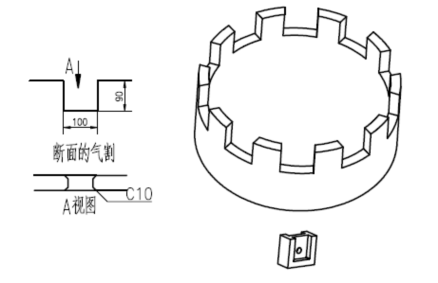
1) Cutting and processing of the tool holder groove: The quality of cutting and processing of the tool holder groove directly affects the welding of the tool holder. Therefore, it is necessary to control the quality of cutting and processing of the tool holder according to the following diagram.
2) Welding of tool holder: After cutting and processing the groove of the tool holder, welding of the tool holder should be carried out. The welding of the tool holder should be firm and there should be no false welding. The height of the weld seam should not exceed the inner and outer walls of the sleeve.
3) Replacement of tool holder: If the tool head is used continuously beyond the wear limit, it may cause wear of the tool holder. After the wear of the knife holder, it is easy for the knife head to be not firmly fixed, causing shaking, affecting the service life and construction efficiency of the blade. In this case, a new knife holder must be replaced.
3. Wear resistant overlay welding of bottom casing
When cutting sandy clay, quicksand, bedrock, block stones, solitary stones, etc., the lower end of the tool holder and bottom sleeve is prone to wear. Therefore, it is necessary to use wear-resistant welding rods to perform wear-resistant overlay welding on the outer wall of the bottom sleeve or weld some high wear-resistant process bars on the outer wall. The function of wear-resistant overlay welding is not only to reduce the wear of the casing, but also to remove cutting residues, smooth the hole wall, and reduce surface friction resistance.
When cutting sandy clay, quicksand, bedrock, block stones, solitary stones, etc., the lower end of the tool holder and bottom sleeve is prone to wear. Therefore, it is necessary to use wear-resistant welding rods to perform wear-resistant overlay welding on the outer wall of the bottom sleeve or weld some high wear-resistant process bars on the outer wall. The function of wear-resistant overlay welding is not only to reduce the wear of the casing, but also to remove cutting residues, smooth the hole wall, and reduce surface friction resistance.
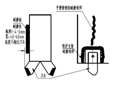
Wear resistant overlay welding schematic diagram
1) Selection of welding rods for overlay welding
During the rotation and compression process of the casing, it is subject to wear and impact from sandy clay, mountain sand, bedrock, block stones, and isolated stones. Therefore, wear-resistant welding rods suitable for the above working conditions should be selected for overlay welding, such as D237 and D246 wear-resistant welding rods, to improve the service life of the bottom casing joint.
D237 chromium molybdenum vanadium steel overlay welding rod, using DC reverse connection, overlay welding hardness HRC: ≥ 50. Used for overlay welding of easily worn parts of hydraulic machinery, engineering machinery, mining machinery, etc. that are damaged by sand and gas erosion.
D246 wear-resistant welding rod, dual-purpose for AC and DC, with a welding hardness HRC of ≥ 60. Used for welding components with abrasive wear and impact load conditions under normal temperature and non corrosive conditions, such as easily worn parts in mining, engineering, agriculture, brick making, cement, water conservancy and other machinery.
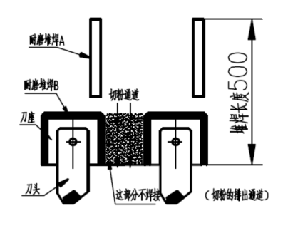
2) Location of wear-resistant overlay welding
The wear-resistant overlay welding position A plays an important role in smoothing the unevenness of the hole wall, ensuring the gap between the casing and the hole wall, and preventing sand and soil from accumulating on the hole wall. The height of the overlay welding layer should not be higher than the protrusion of the cutting edge, with a recommended length of 6-8mm and a control of 500mm or more. The function of wear-resistant overlay welding at point B is to prevent the wear of the tool holder.
3) Chamfer of bottom casing
When using bottom casing for cutting, especially when cutting bedrock, if the slag discharge is not smooth, the cut slag can easily accumulate in the cutting groove, causing a sharp increase in torque, greatly affecting cutting efficiency and reducing construction speed. A chamfer can be set at the lower end of the bottom casing to allow cutting slag to be discharged in a timely manner, improve cutting efficiency, and thus increase construction speed. In order to allow the cutting slag to flow better to the inner side of the casing, a chamfer of 15-20 degrees is selected. To prevent wear on the chamfered part, wear-resistant overlay welding must be carried out on the chamfered part to improve its wear resistance.
When using bottom casing for cutting, especially when cutting bedrock, if the slag discharge is not smooth, the cut slag can easily accumulate in the cutting groove, causing a sharp increase in torque, greatly affecting cutting efficiency and reducing construction speed. A chamfer can be set at the lower end of the bottom casing to allow cutting slag to be discharged in a timely manner, improve cutting efficiency, and thus increase construction speed. In order to allow the cutting slag to flow better to the inner side of the casing, a chamfer of 15-20 degrees is selected. To prevent wear on the chamfered part, wear-resistant overlay welding must be carried out on the chamfered part to improve its wear resistance.